by David Kelly
This is the second in a series of articles outlining the history, advances, and innovations witnessed by the tilt-up construction industry from its inception in the early 1900s through its remarkable growth over the past century.
If it isn’t broke, don’t fix it—a well-worn adage that applies to many parts of the tilt-up process, though maybe none more so than the lifting anchor and clutch—critical components in the erection of concrete panels weighing tens, and sometimes hundreds, of tons.
Because of the trust that contractors have placed in modern lifting systems, their design has changed little in the 50 years since US manufacturers began importing German precast lifting systems the late 1970s and early 1980s.
Like much of the tilt-up history, however, the industry’s early days saw considerable ingenuity, as well as trial and error, when it came to lifting tilt-up panels into place.
Early Anchors
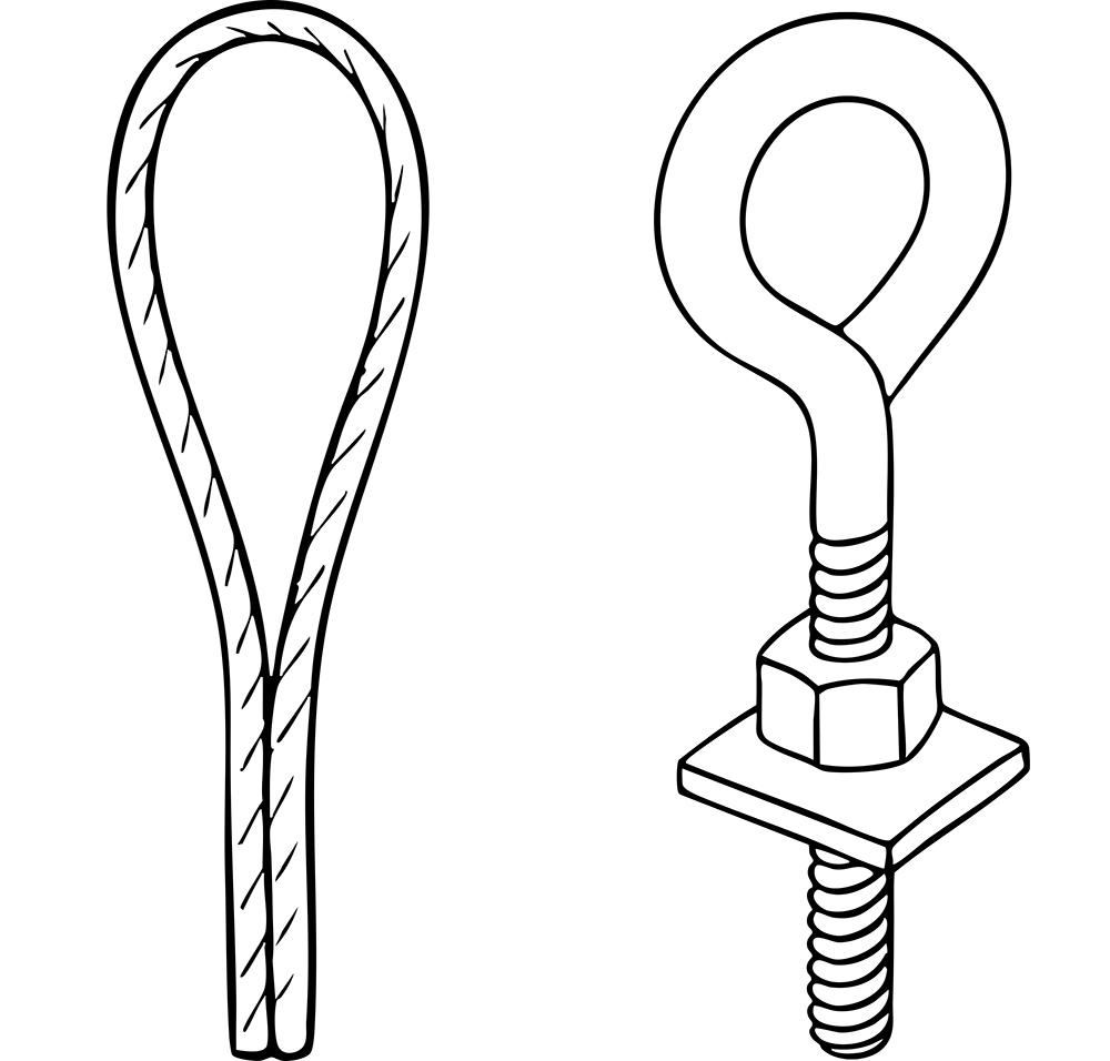
When tilt-up construction accelerated as a building method in Southern California after World War II, there were practically no suitable lifting inserts, so contractors invented their own. Some embedded reinforcing steel or wire rope with a loop projecting through the panel’s face that could be cut off after erection. Others used large eye bolts and accompanying nuts, and cast them into the concrete. If properly greased, the bolt could be removed after the panel was erected, leaving jus d left there.
Each of these systems had significant draw backs. Often, the bolts that had been inserted before the concrete was placed could not be located again once the panel was cast. If they were found, it was not uncommon for them to be unable to be removed. Even if everything went well, the lifting eye bolts could often not be removed due to damage to their fine threads that occurred during the lifting process, which meant they had to be cut off flush with the panel face.
Better Engineering
In the 1950s, the coil bolt and insert appeared. The thread on the insert was made by tightly coiling a wire around a mandrel. This created a thread with a large pitch, which made for easier removal of the bolt. The bolt for this coil had threads that were large and smooth, less likely to be cluttered with concrete, and less prone to damage.
Several manufacturers made coils, bolts, and inserts. They were not consistently interchangeable because the coiled wire diameter controlled the thread profile, and not all were made from the same thickness. There was no formal standard or governing body for this type of thread, so users needed to be certain to use the same brand insert and bolt.
The coil inserts for face lifting panels were many different shapes, but most placed the coil near the surface for easy attachment, with legs going deep into the concrete and with some type of offset to prevent easy removal. The most common shape had four legs, resistance welded to the coils, and then bent near the bottom surface for greater embedment and lifting capacity. The legs were usually welded to the coil in pairs, which aided in achieving the ideal combination of heat, pressure, and duration that were necessary to create this weld. If done poorly, the legs might come off during placement.
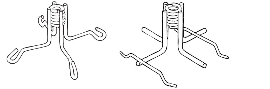
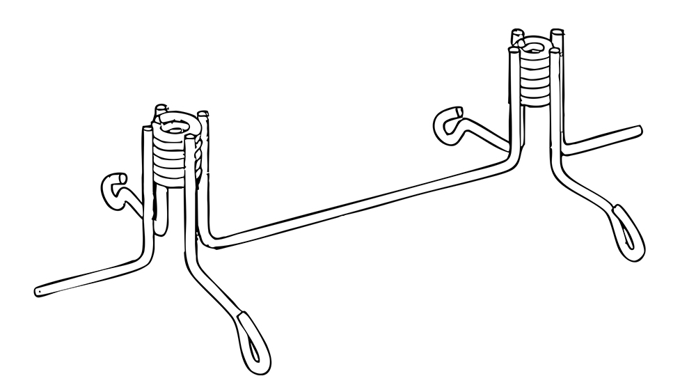
Some of the first popular coil inserts were double coil with two coils in line spaced 10” to 15” apart. An angle plate with a gusset and an eyebolt was bolted to the coils, and the crane hook or shackle was attached to the gusset. This configuration spread the load in the concrete to form either two small cones or one large cone. By changing the length of the legs welded to the coil, the insert could function in different depths of concrete.
The concrete was kept out of the coils while being screeded by inserting a short length of threaded coil rod without a bolt head on it. The top end of the stud had a slot for removal with a screwdriver. This part was commonly referred to as a “slotted lag stud” and was usually greased for easy removal. This stud was supposed to be set slightly below the concrete surface to permit screeding. The grease on the stud made a dark spot in the finished concrete to aid finding the insert for lifting. After erecting the panel, the “angle lift plate” was removed and the hole was patched.
Later studies found that by increasing the diameter of the bolt for shear loads and the diameter of the wire legs for pullout, it was possible to obtain nearly the same load with a single coil as a double coil insert. Contractors preferred the single coil version because they only had to deal with one bolt per insert rather than two during lifting and patching. The single unit was used with a swivel lift plate with a bail rather than the double angle lift plate.
As newer materials were developed, the steel slotted lag stud was replaced with a single-use Styrofoam plug, and then later, a plastic plug. Some of the plastic plugs had whiskers protruding above the concrete for easier locating and other had a sponge that sucked the water out of the concrete that left a dry or white spot.
For top edge lifting of panels that would permit the panel to hang plumb, similar coil inserts were made with different shaped legs to facilitate placing them in the top edge of the panel.
Simplifying the Process
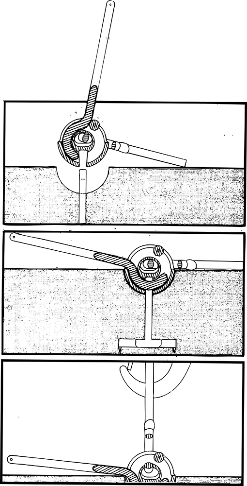
Using coil inserts required cleaning the plug and concrete out of the coil and threading the bolt in to secure the lift plate. This required using either a large wrench or a corded impact wrench. Removing the lift plates required a long ladder and a large wrench or corded impact wrench. The ladder had to be repositioned for each insert in either the narrow area around the crane or between the crane and the panel, which wasted quite a bit of crane time.
By the 1970s, tilt-up contractors were looking for ways to speed up lifting operations by removing the lift plates from the erected panels from the ground, preferably without the use of heavy tools.
One of the first attempts was to use a coil bolt that was split longitudinally into three pieces that were pinned together in a slot. The center piece of the bolt protruded above the head of the bolt and engaged a lever with a lanyard to the ground. After the crane stood the panel and relaxed the load on the insert, the lanyard could be pulled that slipped the center piece out of the bolt and the other two pieces collapsed into the coil while the whole bolt was pulled out. In theory, this worked well and was faster because no one had to climb up and turn the bolt, but the pieces did not always slip easily and the angle of the lanyard was too steep to readily allow the bolt to clear the coil.
Later, lift inserts were developed to eliminate the coil and bolt, instead using a sleeve for the coil and a smooth hollow bar for the bolt. A rod went through the hollow bar and pushed out two spring-loaded steel ears—or four ball bearings, in a later version—into a groove that locked them in the sleeve. After the panel was erected, the rod was withdrawn by a mechanism on the lift plate that utilized a lanyard from the ground. The insert height was adaptable to different concrete depths by changing the leg lengths supporting the sleeve. This system worked well if the mechanism was cleaned and well oiled, but problems arose if dirt and dust got into the system.
Another attempt to eliminate the coil and bolt featured a cylinder with two spaced rods welded across the bottom to support its feet. The two rods were spaced far enough apart so that a T-shaped piece could be slipped down the cylinder between the rods and then turned to lock under the rods. The upper end of the “T” was attached to a short cable with a loop in it. The crane hook, or shackle, was attached to the loop, allowing the short cable to move around the inside of the cylinder and follow the line-of-load of the crane cable. Ground release was obtained by a clevis on a lanyard between the short cable and the crane cable. Unfortunately, the short cable often impinged on the inner cylinder wall and kinked the cable.
Safety Considerations
In 1980, California’s OSHA department began looking at safety for tilt-up equipment and proposed a safety factor of on all reusable equipment like cranes, spreader bars, cables, shackles, and hooks. It also proposed a safety factor of four on lifting inserts and a 1,000-lb load limit on embedded reinforcing bars or cables.
Industry advocates, including at least two manufacturers, convinced them that the safety factor of four was fine for precast concrete where the lifting inserts are used multiple times, but that a safety factor of two was more appropriate for tilt-up inserts that are only used once. California’s OSHA department agreed, and these safety factors were adopted—the only lifting regulations for the tilt-up industry for years. Later, other agencies reviewed safety in tilt-up and adopted similar safety factors.
Modern Inserts
By the late 1970s and early 1980s, a better lift system solution was found in Germany, where two companies had seen success with competing concepts for precast concrete lifting systems. These new designs quickly made their way across the Atlantic for use in American projects.
Both imports boasted a similar allure for US tilt contractors; they were strong and durable, didn’t rely on small parts or field lubrication, and their clutch could be modified to be remotely released.
The Frimeda system was patented in Germany in 1963. It uses a shackle attachment or “clutch” that passes a curved bolt through a hole in a vertical steel bar—the anchor—cast into the concrete panel but later accessible thanks to its removeable plastic void former around the anchor’s head. This clutch is inserted into the anchor much the same way a simple necklace clasp is inserted through a link in a necklace.
The bottom half of the donut-shaped piece of the clutch bears inside the concrete when the load is applied anyway but vertically. The inside of the hole becomes the bearing point for the clutch, which eliminates any surface marking. The insert is released from the ground with a lanyard on the long handle of the clutch. The insert height is adjusted by the embedded steel bar length and supporting feet. The strength in the concrete can be varied by increasing the depth in the concrete and the configuration of the vertical bar. The insert and clutch are available in different strengths by thickening the steel bar and increasing the clutch diameter. The shape of the steel bar that has been used in tilt-up has changed from a T to an S, and finally to a V to obtain ease of manufacture and increased pull-out strengths.
The Deha system was also patented in Germany in the 1960s. Its insert looks like a forged double-headed concrete anchor or HCA. The bottom head—usually the larger and flatter of the two ends—is snapped into a wire or plastic base to support it vertically and hold it off the bottom face of the concrete. The upper head has a plastic, protective cover that forms a depression for the clutch. The clutch has a bail, a ball with a hole, and a slot in it. The hole in the ball slips over the head and is rotated until the anchor shaft is in the slot. The insert is released from the ground with a long handle on the clutch. The ball of the clutch bears inside the depression formed in the concrete to form a bearing point to eliminate surface marking. As with the previous insert, the strength in the concrete can be increased by increasing the depth in the concrete. The insert and clutch are available in different load capacities by varying the basic insert and clutch diameters.
Now found on virtually every tilt-up job site, these two lifting systems, with minor variations, are almost identical to the designs developed by German engineers in the 1960s and imported into North America in the 1980s.
They are simple to use, require little maintenance, are incredibly strong, and have experienced few, if any, failures when properly installed in the millions of tilt panels erected over the past five decades.
Be the first to comment