By JAMES R. BATY II | Images courtesy of Big-D Construction
The design of temporary bracing for tilt-up panels, like engineering the panels themselves, stays free of anything dealing with means and methods. As with any construction project, these are a contractor’s responsibility with little to no guidance from standards or regulations. This article provides the reader with some concepts to consider when developing a company policy or best practice for training and implementation of brace removal.
Throughout the world, agencies and administrations establish regulations for employers involved in construction activities to provide protection for their workforce. In Canada, this is achieved through the Canadian Federation of Construction Safety Associations (CFCSA). In Australia, it is Safe Work Australia and in the United States, the Occupational Safety and Health Administration (OSHA). Part of your duty as an employer is to identify with the appropriate governing body in a given jurisdiction to fully understand what procedures and policies must be in place to educate, train and maintain a safe workforce.

OSHA, as an example, requires contractors engaged in the act of building with precast concrete panels, which includes tilt-up or tilt-wall panels cast on jobsites, to comply with the requirements set forth in 1926.704. This is a relatively short section considering typical construction safety regulations, consisting of only a few subparts. The first subpart states simply: “Precast concrete wall units, structural framing, and tilt-up wall panels shall be adequately supported to prevent overturning and to prevent collapse until permanent connections are completed.” While no other clarifying direction is presented in the regulation, OSHA continues in its Safety and Health Information Bulletin, SHIB 10-15-2003 titled “OSHA Standards and Suggested Safety Tips for Tilt-up Construction,” where direction is given about maintaining bracing until the roof structure or columns are in place and can adequately stabilize the building. In other words, OSHA states that until the final building connections can complete the structural shell of the building for permanent stability, the contractor should maintain bracing to prevent the panels from falling down. TCA provides guidance in its document, “Guidelines for the Design of Temporary Wind Bracing for Tilt-Up Panels,” on how to achieve this condition and how to interpret other governing regulations for what forces shall be achieved using ASCE 7 for applied loads.
What the OSHA regulations do not address, however, is the more detailed means and methods related to performing work functions such as installing and removing the braces. During these parts of the construction process, workers are arguably exposed to greater risk than working around a temporarily-braced shell. Since the general duty of an employer is to provide for safe working environments and to protect their workforce, TCA provides the following information on removing the temporary panel braces.
The Current Industry
Today, pipe braces for tilt-up or tilt wall construction vary substantially in length and weight. The length, and therefore weight, of the brace is determined by the panel engineer, including associated approved fasteners. Tilt-up panels now have been constructed to be over 100 feet in height and the average height of tilt-up buildings has now risen to just under 50 feet. Building size, crane size, site restrictions, and the panel geometry have the most influence on the number of panels for a project. With the building areas presented for some of these large projects, or the heights of some of these mid-rise office buildings, brace removal is a large, time-consuming task that can become an obstacle to the project schedule. The pressure mounts on the contractor responsible for removing these braces.
A panel brace is typically connected at the ground level by one of two means: it is bolted to the floor slab or it is anchored in the ground by connection to a helical ground anchor (HGA) or an engineered concrete deadman. Prior to erection of the tilt panel, the braces are most often connected to cast-in inserts exposed on the topside, interior face of the panel. However, braces may also be attached to the panel after it is in its final vertical position, often on the exterior face of the panel, such as multi-story panels braced to helical ground anchors. This allows for the structural framing to commence without any brace interference.

The Process
Once the structural diaphragms and details are completed and the Engineer of Record has provided written guidance, the contractor or erector responsible for brace removal begins the systematic process.
The following is a list of criteria established by the TCA for contractors to consider in determining their specific approach to brace removal on any particular project. They influence the approach to effectively and safely disengage a brace from a panel and lower it to the ground where it can be picked up with material handling equipment for storage or shipping.
- Site Conditions: Many unique conditions exist for bracing schemes and the specific removal locations can vary from project to project as well as within any given project. For instance, bracing to an interior slab offers a clean working surface where boom and scissor lifts maneuver uniformly. However, bracing to the exterior face of the building means that access to the braces offers challenges in levelness and soil condition such that a contractor may need to use lift or handling equipment specifically designed for such terrain.
- Equipment Capacity: Each piece of equipment has published safe working loads and reaches capacity to consider along with its maneuverability within a given terrain or environment. Knowing the working weights of the braces and their capacities is important for lowering braces.
- Brace Condition: Over the time a tilt-up panel has been braced, the brace itself has been placed into tension or compression, known as “brace bind.” Whether the braces were tightened initially for final plumb adjustments, wind loads or daily brace maintenance, this force can exist and the stress must be relieved or released before proceeding. If allowed to remain while starting to release a brace end, the force may cause the brace itself to move suddenly or uncontrollably.
- Determine Start End: Brace removal should then proceed by disengaging one end of the brace at either the ground level or the panel elevation. Most contractors simply loosen the fastener at the brace foot bolt (to the slab) to allow the shoe to slide out, or remove the bolted connection to the HGA and set the end of the brace on the ground. When the lower shoe is loosened first, a contractor may set the brace shoe on wheels for quick movement or have it carried by a worker(s) in a sling. The brace, however, may instead be loosened by loosening the bolt at the face (shorter panels) so that the upper brace shoe can slide out.
- Control the Top: A suitable strap or large rope is often used to secure the top of the brace to the equipment selected for lowering the brace to the ground. This is attached from the brace shoe to or through the device used to control the rate of decent, without fear of slipping out. Note, however, that lift equipment manufacturers do not allow you to do this under their equipment warranties; most warranties state that you are not allowed to utilize their frame/baskets for such activities. Some lift manufacturers make forks that they will allow you to use for this purpose, but like the braces themselves you cannot use differing manufacturer’s products. Be sure to consider this with the equipment you select.
- Final Connection: Prior to lowering the brace, a final check to be sure it is free from any connections is completed, most often resulting in removal of the bolt from the panel face holding the top shoe. The equipment provides stability to the upper end of the brace and shares the weight of the brace with the selected ground support.
- Movement: Lower the brace at a controlled rate to the ground.
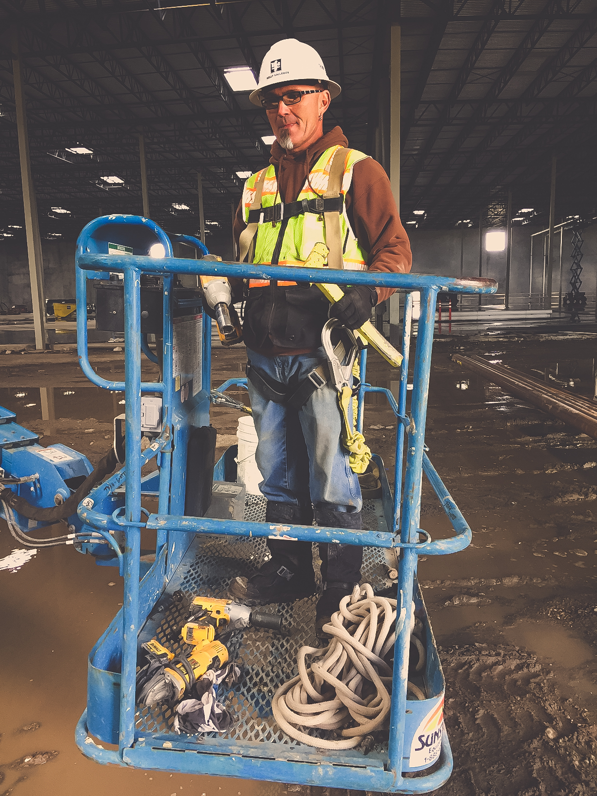
There are many ways to achieve a suitable process that delivers results according to these parameters. Many different pieces of equipment might be used such as scissor lifts, boom lifts, zoom lifts, jib cranes, telescopic forklifts, etc. Every contractor will be responsible for and knowledgeable of procedures that are more specific to their application, experience and equipment availability. The example procedure below has been provided by a member of the TCA Safety Committee, offering a look at one approach to a specific project solution:

Equipment
- Appropriately-sized vertical lift equipment, capable of handling the loads and purpose of the intended operations.
- Two (2) – ¾-in. impact wrenches (one with worker on the lift and one with worker on ground). Cordless appears to be the preferred tool of choice.
- Two (2) – ¾-in. standard wrenches (one each in the event of equipment failure).
- ¾-in. diameter rope with at least 25% more length than the height above the ground.
Crew
- Two (2) workers – one on ground and one in lift.
Note: crew size varies based crew experience and site-specific challenges that maybe present.
Procedure
- Raise the selected lift to the elevation that puts the top of the boom lift basket just below the brace to panel shoe.
- Tie an end of the rope secure to the brace at the top of the brace just below the brace shoe.
- Wrap the rope around the top rail of the boom lift basket one time, without slack to the brace shoe. This will allow for proper friction on the rope to lower the brace to the ground from the boom lift basket.
- After the rope is tied to the brace and wrapped one time around the basket, the person in the boom lift removes the panel to brace bolt from the inside of the basket.
- Once the panel to brace bolt is removed then the person in the boom lift basket holds the rope securely.
- Then the ground person removes the brace to floor bolt on the brace.
- Once this brace to floor bolt is removed, the ground person will assist this brace to the ground as the person in the lift lowers the brace to the ground with the rope that is wrapped around the basket one time. Notice that the boom lift is not used to lower the brace against its hydraulic capacity—the lift stays securely positioned in its height and an even friction and tempo in the rope is used.
- Repeat this process on the next brace.
This procedure is a specific interpretation by a contractor on the task of lowering braces for a specific project. It was, however, influenced by their experiences across multiple projects and is part of their standard approach. The most important aspects of the process are clear in each of their approaches and for those the TCA sees in each certified company and many safety plans. The brace bind is released; one end is loosened and disengaged; the top of the brace is secured to a strong and controlled position; the brace shoe at the panel is released; and the brace is carefully lowered at a controlled rate. During the safety meeting, workers should be cautioned and educated on working around ropes and slings during this process.
TCA Cyber Roundtable
As a means of connecting members more closely in regular conversation, the TCA established an email communication network for individuals employed by member firms, known as the TCA’s Cyber Roundtable. This networking tool permits individuals to contact headquarters by email (which is preferred) but sometimes by phone, and initiate a discussion on any topic related to tilt-up design, construction or business engagement. A wide variety of topics have been discussed since the inception of the Cyber Roundtable and recently the topic of safe brace removal has been discussed multiple times following worker injury. Through consecutive layers of input on this topic and the recent updates of the TCA Wind Bracing Guidelines, this information has been presented as a recommendation from the TCA, offering the industry a position on safely removing braces that are large, heavy, cumbersome and at times hazardous to handle if not treated with the respect they deserve.
Want to know more? Contact TCA’s Manager for Regulatory and Technical Affairs, Jim Baty at 319-895-6911 or by email at jbaty@tilt-up.org. The mission of the Tilt-Up Concrete Association is to expand and improve the use of tilt-up as the preferred building system by providing education and resources that enhance quality and performance. More information can be found at the association website, www.tilt-up.org.
Be the first to comment